CHS
CHS Walsun Mall
Support

 Knowledge Base +
  2024.01.24
Customers in the use of optical modules will more or less encounter a variety of failure problems, such as optical module model selection is correct, the use of jumper is correct and some common problems, customers have the ability to judge and have a clear solution, but for some of the use of failure problems, such as transmission abnormalities, etc., many customers do not know how to troubleshoot and solve. In this article, we will focus on teaching you how to troubleshoot and solve the common three categories of optical module failure.
First, the transmission class of the optical module fault investigation and solution method
This type of optical module failure mainly includes port not UP, port status is UP but do not receive or send messages, port frequently up or down and CRC error. Specific troubleshooting methods and solutions for optical modules are as follows:
1. Port not UP
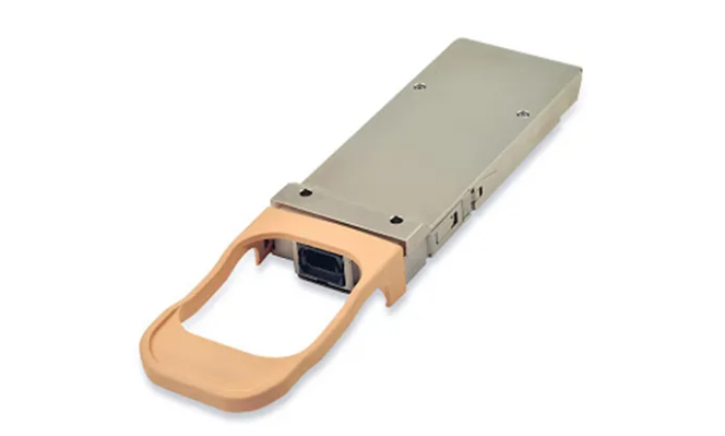
Taking 10G SFP+/XFP optical module as an example, when the optical port of the optical module can not be UP when interconnecting with other devices, it can be troubleshooted from the following five aspects:
The first step is to check whether the rate and duplex mode of the ports at both ends match - execute the "show interface brief" command to check, and if they do not match, configure the rate and duplex mode of the ports through the speed command and duplex command. rate and duplex mode.
Step 2 Check whether the rate and duplex mode of the device port and the optical module match - execute the "show interface brief" command to check, if they do not match, configure the rate and duplex mode of the port through the speed command and duplex command. If there is no match, configure the rate and duplex mode of the port through the speed command and duplex command.
Step 3 Check whether the ports at both ends are normal - Test whether the ports at both ends can be UP through loopback by interconnecting the 10G SFP+ ports on the single board with 10G SFP+ direct-connect cables (suitable for short-distance connection, or use SFP+ optical modules and fiber patch cords), and use XFP optical modules and fiber optic cables for 10G XFP ports to test and check whether the 10G XFP ports can be connected to the single board. module and fiber optics on the 10G XFP port to test whether the port can be UP; if it can be UP, it means that the opposite port is abnormal; if it cannot be UP, it means that the port on the local end is abnormal. You can check whether the problem is solved by replacing the local port and the opposite port.
Step 4, check whether the optical module is normal - mainly check whether the parameters of DDM, optical power, wavelength, distance, etc. are normal, if they are not normal, then by replacing the optical module that matches the optical interface.
DDM information - check whether the parameters are normal through the "show interfaces transceiver detail" command, if there is an alarm, it means that the optical module is faulty or the optical module does not match the optical interface type. If an alarm appears, it means that the optical module is faulty or the optical module does not match the optical interface type.
Optical Power-Use the optical power meter to test whether the power received by the port is within the normal range and stable.
Wavelength/Distance - Check whether the wavelength and distance of the optical modules at both ends are the same through the command "show transceiver interface".
The fifth step, check whether the fiber is normal - such as, single-mode SFP + optical module with single-mode fiber, multi-mode SFP + optical module with multi-mode fiber, if the mismatch immediately replace the matching fiber can be.
If you still can't find the cause of optical module failure or solve the problem of optical module failure according to the above steps, it is recommended that you directly contact the supplier's technical staff to seek technical help.
2、Port status is UP, but does not receive or send messages
When the port status is UP, but it does not receive or send messages, troubleshoot from the following three aspects:
The first step is to check the port message statistics. Check whether the port status is always UP at both ends, and detect whether the message statistics grow at both ends.
The second step is to check whether the port configuration affects the reception of messages. First, check whether the network configuration has been done to verify whether the configuration is correct, and if necessary, delete all of them and test again to see whether the problem is solved; second, check whether the port MTU value is 1500, and if it is greater than 1500, you need to modify the configuration.
The third step is to check whether the port and link cutoff are normal. Replace the connection port and connect it to other ports to see if the same phenomenon exists; if it is still faulty, replace the optical module.
If the problem of optical module failure is still not solved after following the above steps, it is recommended that you contact the supplier's technical personnel directly.
3、Frequent port up or down
When the optical port of the optical module is frequently up or down, first confirm whether the optical module is abnormal, you can check the optical module alarm information to troubleshoot the optical module at both ends and connect the optical fiber; for the optical module to support digital diagnostic function, you can check the DDM information to confirm whether the optical power of the optical module is in the critical value, if the transmitter optical power is in the critical value, then replace the fiber, the optical module as a cross-check. If the transmit optical power is in the critical value, then replace the optical fiber and optical module as cross-checking, and if the receive optical power is in the critical value, then check the optical module at the opposite end and the connecting fiber. When the situation occurs in the optical module of the electrical port, try to set the rate duplex.
If the optical module failure still exists after troubleshooting the link, terminal equipment and intermediate equipment, it is recommended that you directly contact the supplier's technical staff.
4、CRC Error
The first step is to check the message statistics to determine the problem. Through the "show interface" command, view the wrong packet statistics in the inbound and outbound directions of the port to determine the volume of which growth, so as to determine the problem.
CEC, frames, wrong packets in the inbound direction of the port and the count continues to increase - use the instrument to test whether the link is faulty, if it is faulty, then replace the cable or optical fiber; or replace the cable or optical fiber optical module and other ports connected to the port, if it is the port after the replacement of the wrong packets and reoccur, it is considered to be the single board port If the error packet reappears after port replacement, it is considered as a single board port failure. If the error packet still occurs even if the port is replaced to a normal port, then the possibility of failure of the opposite end equipment or intermediate transmission link is higher, and it can be investigated.
Check whether there are overrun error packets in the inbound direction of the port and the count continues to increase - by repeatedly executing the "show interface" command to check whether the input errors have increased, if so, it means that the overruns have increased, and the single board port is considered a single board port failure. If so, it means that overruns are increasing and the board may be congested or blocked.
Check whether there are giants error packets in the inbound direction of the port and the count continues to increase - check whether the Jumbo configurations at both ends are consistent, such as whether the default maximum message length of the port is the same, and whether the maximum allowable message length is the same, and so on.
The second step is to check whether the optical power of the optical module is normal. Check the current measured value of the digital diagnostic parameters of the optical module inserted in the optical port through the command "show transceiver interfaces detail". If the optical power of the optical module is not normal, you need to replace the optical module.
Step 3: Check whether the port configuration is normal. Through the "show interface brief" command to check whether there is any abnormality in the port configuration, in which the negotiation status of both ends of the duplex mode and the port rate is the same, if there is a half-duplex mode or rate inconsistency, then configure the duplex mode and the port rate through the duplex command and the speed command, respectively. rate.
Step 4: Check whether the port and link media are normal. Replace the connected ports to see if the same phenomenon exists; if the same phenomenon exists, check whether the intermediate devices and transmission media in the connected link are normal; if they are normal, replace the optical modules.
Step 5: Check whether the port receives a large number of flow control frames. Through the "show interface" command, check the pauses frame count of the port, if it is growing, it means that the port has sent or received a large number of flow control frames. In addition, check whether the incoming and outgoing traffic of the port is too large and the traffic processing capability of the peer device.
After the above checking, if there is no problem with the configuration, the peer and the link, but the optical module failure problem still exists, then please contact the technical support personnel of the vendor directly.
Additional Learning Hub Resources
How do you connect fiber optic cable to SFP
What is the difference between Gigabit and 10 Gigabit Optical Modules
Oscilloscope Voltage Probe Accuracy Analysis Details
What signals does fiber optics transmit How does fiber optics transmit data
What is structured cabling in a network system A guide for beginners
10G Copper SFP+ SFP+ to RJ45 Solution for beginners
Subscribe to the newsletter
for all the latest updates.


2-5# Building, Tongfuyu Industrial Zone, Aiqun Road, Shiyan Street, Baoan District, Shenzhen. China


_1702362302.png)