CHS
CHS Walsun Mall
Support

 Knowledge Base +
  2024.01.30
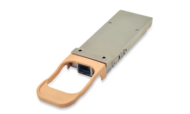
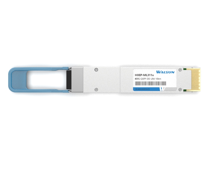
QDD-400G-SR8 Transceiver is a parallel 400Gb/s quad small form-factor pluggable double density (QSFP-DD) optical module. It enhances port density and saves overall system costs. The QSFP-DD full-duplex optical module provides 8 independent transmit and receive channels, each capable of operating at speeds of 53.125Gb/s aggregating to 400Gb/s data rate over 100 meters OM3 multimode fiber.

Figure:400G QSFP-DD
Fiber optic cables with MTP/MPO-16 connectors can be inserted into the QSFP-DD SR8 module socket. The latch inside the socket ensures proper alignment. Cables typically cannot properly twist channel-to-channel alignment. Electrical connection connectors are implemented via edge type conforming to the QSFP-DD MSA standard. The center wavelengths of the 8 parallel lines are 850nm. It incorporates an optical MPO-16 connector for the optical interface and a 60-pin connector for the electrical interface. Host FEC support is required for OM3 multimode fiber transmission up to 70m. The module's form factor, optical/electrical connections, and digital diagnostics interface follow the QSFP-DD Multi-Source Agreement (MSA) type 2.
It is designed to meet the most stringent external operational conditions, including temperature, humidity, and EMI interference. The optical module consists of 8 parallel channels, with a center wavelength of 850nm, each running at 50G. The transmitter path includes an 8-channel CDR retimer, 2 sets of four-channel VCSEL drivers, and 2 sets of VCSEL arrays. On the receiver path, 2 sets of photodiode array optical devices are coupled with an 8-channel CDR retimer. The electrical interface conforms to IEEE 802.3bs and QSFP-DD MSA in both transmit and receive directions, while the optical interface conforms to the QSFP-DD MSA with MPO-16 optical connectors.
A single +3.3V power supply is required to power this product. All power pins are internally connected and should be applied simultaneously. According to the MSA specification, the module (Gigabit optical module) provides seven low-speed hardware control pins (including a 2-wire serial interface): ModSelL, SCL, SDA, ResetL, InitMode, ModPrsL, and IntL.
The module selection (ModSelL) is an input pin. When the host maintains a low level, the product responds to 2-wire serial communication commands. ModSelL allows the use of this product on a single 2-wire interface bus—a separate ModSelL line must be used. The 2-wire serial bus communication interface requires a serial clock (SCL) and serial data (SDA) and enables the host to access memory-mapped registers.
When the low level on the ResetL pin is maintained for longer than the minimum pulse length, the ResetL pin can achieve a full reset, returning the settings to their default state. During the reset execution, the host should ignore all status bits until it indicates that the reset interrupt is complete. The product indicates this by issuing an IntL (interrupt) signal, where the Data_Not_Ready bit is inverted in the memory map. Note that during power-up (including hot insertion), the module should issue this reset interrupt completion without requiring a reset.
Initialization mode (InitMode) is an input signal. It is pulled up to Vcc in QSFP-DD modules. The InitMode signal allows the host to define whether the QSFP-DD module is initialized under host software control (InitMode asserted high) or module hardware control (InitMode low). Under host software control, the module should remain in low-power mode until software supports transitioning to high-power mode, as defined in the QSFP-DD Management Interface Specification. In hardware control (InitMode low), the module may transition to high-power mode immediately after initialization of the management interface. The host must not change the state of this signal when the module is present. In traditional QSFP applications, this signal is named LPMode.
Module presence (ModPrsL) is a local signal on the host board, typically pulled up to the host Vcc in the absence of the product. When the product is inserted into the connector, it (10 Gigabit optical module) completes a ground path via resistors on the motherboard and sends a signal. ModPrsL then indicates its presence by setting ModPrsL to a "low" state.
Interrupt (IntL) is an output pin. "Low" indicates possible operational faults or states critical to the host system. The host uses the 2-wire serial interface to identify the interrupt source. The IntL pin is an open-drain output and must be pulled to the host Vcc voltage on the motherboard.
Additional Learning Hub Resources
How to choose an appropriate optical fiber jumper for the QSFP-DD 800G optical module
Cisco 400G QSFP-DD Optical Transceivers Overview
Subscribe to the newsletter
for all the latest updates.


2-5# Building, Tongfuyu Industrial Zone, Aiqun Road, Shiyan Street, Baoan District, Shenzhen. China