CHS
CHS Walsun Mall
Support

 Knowledge Base +
  2024.01.16
According to different transmission distances, 800G QSFP-DD optical modules are divided into SR, DR, FR, LR, ER and ZR, which can achieve different distance transmission on single mode (SMF) fiber or multi-mode fiber (MMF). In general, two 800G QSFP-DD optical modules are inserted respectively into the corresponding switch ports, and then connected with a single mode or multi-mode optical fiber to achieve the 800G transmission rate. However, for the 800G QSFP-DD optical module, the optical port type of the same type of optical module may be different between different manufacturers.
>>> To learn more What are the 4 common fiber optic connectors?
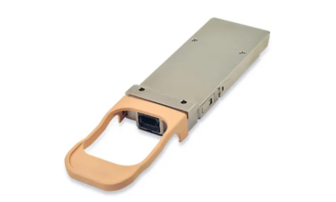
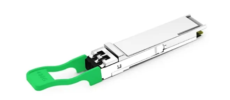
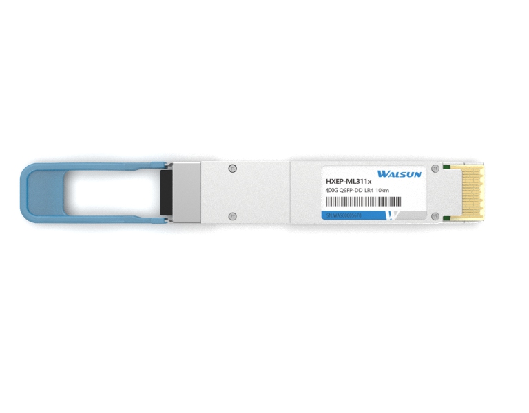
800G QSFP-DD optical port type
The optical ports on the 800G QSFP-DD optical module are classified into duplex LC ports, VSFF ports (SN, CS, and MDC), and MPO ports (MPO-12, MPO-16).

Select a jumper for an 800G optical module
Transmission mode: Select single-mode fiber jumper or multi-mode fiber jumper (OM3, OM4, or OM5) based on the transmission mode of the optical module.
Fiber jumper polarity: For network links, it is necessary to ensure that the transmitter and the receiver are connected to ensure that the signal can be correctly transmitted. In high density cabling, MPO fiber jumper is composed of multiple fiber cores, and the polarity of the fiber core is different. Therefore, great attention must be paid to the polarity selection of MPO fiber jumpers (the TIA standard defines Type A, Type B and Type C polarity).
>>> To learn more What type of connector is a Cisco QSFP 40G SR4
MPO fiber jumper Male connector has two pins, while female connector does not. The connection between the MPO connectors is precisely aligned by the PIN pin, and the two MPO connectors connected to each other must be one male and one female.
Link loss: The planning of optical fiber link loss is very important for integrated cabling. A link can run properly only when the link loss value is within the power budget.

Subscribe to the newsletter
for all the latest updates.


2-5# Building, Tongfuyu Industrial Zone, Aiqun Road, Shiyan Street, Baoan District, Shenzhen. China