CHS
CHS Walsun Mall
Support

 Knowledge Base +
  2024.01.16
Optical fiber connectors are essential to the largest amount of optical passive devices, its role is to connect optical fiber with optical fiber, optical fiber and devices (including active devices, passive devices and optical fiber sensors), optical fiber and instrumentation, optical fiber and system together. Wherever there is fiber optic, there are fiber optic connectors. The cladding diameter of the single-mode fiber is ①125p.m(equivalent to the thickness of the hair), and the diameter of the core is only 9 bucket m(the core is the part of the optical fiber), the task of the fiber connector is to accurately butt the core of the 1 9 bucket m together, so that most of the light can pass through, which is technically difficult. Since the optical fiber connector is also a lossy product, it is also required to be cheap.
In the optical fiber communication (transmission) link, in order to achieve the needs of flexible connection between different modules, devices and systems, there must be a removable (active) connection device between the optical fiber and the optical fiber, so that the optical signal can be transmitted according to the required channel to achieve and complete the predetermined or desired purposes and requirements, the device to achieve this function is the optical fiber connector. The optical fiber connector is to precisely dock the two end faces of the optical fiber, so that the light energy output of the transmitting optical fiber can be coupled to the receiving optical fiber to the maximum extent, and to minimize the impact on the system due to its involvement in the optical link, which is the basic requirement of the optical fiber connector. To a certain extent, the quality of the optical fiber connector also affects the reliability and performance indicators of the optical transmission system.
The main use of optical fiber connector is to realize the connection of
optical fiber, and it has been widely used in optical fiber communication
systems, and there are many kinds of optical fiber connectors with different
structures. However, the basic structure of various types of fiber optic
connectors is consistent, that is, the vast majority of fiber optic connectors
generally use high-precision components (composed of two pins and a coupling
tube, a total of three parts) to achieve the alignment of the fiber connection.
In this method, the optical fiber is threaded and fixed in the pin, and the
surface of the pin is polished, and the alignment is realized in the coupling
tube. The outer components of the pins are made of metal or non-metal materials.
The butt end of the pin must be ground, and the other end is usually supported
by a bend limiting member to support the optical fiber or optical fiber cable to
release stress. Coupling tubes are generally made of two synthetic, tight
cylindrical components made of ceramic or bronze and other materials, and are
equipped with metal or plastic flanges to facilitate the installation and fixing
of connectors.
In order to align the fiber as accurately as possible, the processing accuracy of the pin and coupling tube is required.
The technical specifications of optical fiber connectors mainly include the following:
(1) Insertion loss: It indicates the size of the optical power loss after the light passes through the optical fiber connector. It's denoted by dB.
LI= -1019 (11/10), where IO is the input optical power; 11 Indicates the optical output power, which should not exceed 0.5dB.
(2) Repeatability: the change value of insertion loss after repeated insertion. It's denoted by dB.
(3) Interchangeability: After the plug and adapter are exchanged according to certain rules, the change value of the insertion loss.
(4) return loss: It represents the ratio of backward reflected light to incident light after the light passes through the optical fiber connector. It's denoted by dB. Its typical value should be no less than 25dB. The actual application of the connector, the pin surface has been specially polished, can make the return loss greater, generally not less than 45dB.
LR= 1 lOlg(I inverse /IO), where 10 is the input optical power; I inversely represents backward reflected light power.
(5) Temperature range: generally in a 30 ~ +70. Can be used within the range of C.
(6) Tensile strength: indicates how many kilograms of tension can be borne, China's relevant standards stipulate that the tensile strength of a single fiber cable jumper is greater than 10kg.
(7) Insertion and removal times. Currently used fiber optic connectors can generally be plugged and unplugged more than 1000 times.
According to different classification methods, optical fiber connectors can be divided into different types, according to the different transmission media can be divided into single-mode optical fiber connectors and multi-mode optical fiber connectors; According to the different structure can be divided into FC, SC, ST, D4, DIN, Biconic, MU, LC, MT and other types; According to the pin end face of the connector, it can be divided into FC, PC(UPC) and APC; According to the number of fiber cores, there are single core and multi-core points.
In the actual application process, we generally distinguish according to the different structure of optical fiber connectors. At present, the more common optical fiber connectors are:

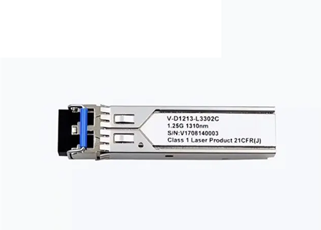
(1)FC optical fiber connector
The FC connector adopts a metal thread connection structure, and the pin body adopts a precision ceramic pin with an outer diameter of 2.5ram. According to the different shape of the pin end face, it is divided into two structures: FC/PC with spherical contact and FC/APC with oblique spherical contact. FC connector is currently the world's largest use of the variety, is also the main variety used in China. FC connectors are widely used in optical cable trunk systems, where FC/APC connectors are used in applications requiring high return loss, such as CATV networks. Our country has established the national standard for FC type connectors.
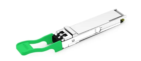
(2)SC optical fiber connector
SC connector is designed and developed by Japan's NrITI 'company, using a plug-in structure, the shell is a rectangular structure, the use of engineering plastic manufacturing, easy to make a multi-core connector, the pin body is a precision ceramic pin with an outer diameter of 2.5mm. Its main characteristics are that it does not require threaded connection, direct insertion and removal, small operating space, and easy to intensive installation. According to the end shape of the pin, it can be divided into two structures: spherical contact SC/PC and oblique spherical contact SC/APC. SC connectors are widely used in optical fiber subscriber networks. China has formulated a national standard for SC connectors.
(3)ST type optical fiber connector
The ST connector is designed and developed by AT&T, using a bayon-type locking structure with a key, the pin body is a precision ceramic pin with an outer diameter of 2.5mm, and the end shape of the pin is usually a PC face. Its main feature is that it is very convenient to use, and it is used in a large number of optical fiber user networks. Our country has formulated the national standard of ST/PC connector.
(4)DIN47256 fiber optic connector
This is a connector developed in Germany. The pin and coupling sleeve used in this connector have the same structural size as the FC type, and the end face is treated by PC grinding. Compared with the FC connector, its structure is more complex, and the internal metal structure has a spring that controls the pressure, which can avoid damage to the end surface due to excessive inserting pressure. In addition, the mechanical accuracy of this connector is high, so the insertion loss value is small.
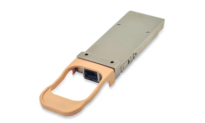
(5) MT-RJ connector
Mt-rj started from the MT connector developed by NTT, with the same latch mechanism as the RJ-45 LAN electrical connector, through the guide pin mounted on both sides of the small sleeve to align the optical fiber, in order to facilitate the connection with the optical transceiver, the connector end fiber is double-core (0.75mm apart) arrangement design. It is mainly a next-generation high-density optical connector for data transmission.
(6)LC connector
LC connector is the famous Bell Institute research and development of the size of the pin and sleeve used is half of the size used by ordinary SC, FC, etc., is 1.25mm. This can improve the density of the optical fiber connector in the optical distribution frame. At present, in terms of single-mode SFF, LC type connectors have actually occupied a dominant position, and the application of multi-mode is also growing rapidly.
(7)MU connector
Miniature unit Coupling (MU) connector is the world's smallest single-core fiber optic connector developed by NTT based on the most used SC connector at present. The connector uses a 1.25mm diameter sleeve and self-holding mechanism, which has the advantage of high-density installation. Using the MU's 1.25mm diameter bushing, NTT has developed a family of MU connectors. They are available as receptacle-type optical connectors for cable connections (MU-A series), baseboard connectors with self-holding mechanisms (MU-B series), and simplified sockets for connecting LD/PD modules to plugs (MU-SR series). With the rapid development of optical fiber networks in the direction of larger bandwidth and larger capacity and the wide application of DWDM technology, the demand for MU connectors will also grow rapidly.
Example 1: For a new optical node, the user reported that the signal of adding channel 3 was poor and there was interference.
Analysis and overhaul. The optical power of the optical receiver was measured by the optical power meter as 1.3dB, and the optical power was in the normal range. The output level of the optical receiver was detected by the spectroscope and no abnormality was found. The signal was taken from the 20dB test port of the optical receiver and monitored by the TV set. The fault point may be determined in the machine room at the front of the branch, and the light spot is found to be emitted by a six-minute optical splitter in the machine room, while other light spots with the same optical splitter do not have this phenomenon. The light spot is exchanged with another normal light spot splitter fiber, and the fault is still found, while the other light spot signal is normal, and it is determined that the optical splitter is not faulty. Because the optical cable is connected to the distribution box in the front computer room, and then connected to the splitter through the live connector, it is suspected that the live connector is faulty, and the fault is removed after replacing the new live connector. The reason for the above failure may be that the accuracy of the live joint connection is not high, causing reflection and causing interference.
Example 2: A light point user complained that the TV signal in the area was seriously snowflake.
Analysis and overhaul. After the optical transceiver is turned on, the optical power of the optical receiver is measured by the optical power meter as 1 2.0dB, which is within the normal range. After careful observation inside the optical transceiver, it is found that the connection between the pigtail connector and the connector of the photoelectric conversion module is loose, unscrew the optical fiber connector, clean it with a medical cotton soaked with anhydrotic alcohol, and tighten it again. The output level of the optical machine is 105dB, and the fault is removed.
With the continuous development of optical fiber communication technology, the application of optical fiber connectors in optical fiber systems will be more extensive. Optical fiber connectors will play an indispensable role in optical fiber communication together with optical attenuators, optical isolators and other optical passive devices.
Example 3: The cable route needs to be changed temporarily. The cable from point A to point B passes through three transmission front equipment rooms, and optical fiber live connectors are used to jump in each room. After the link is restored, a data service cannot be restored.
Analysis and overhaul. Since the link has been tested with OTDR before the recovery of the core, to confirm the connection, first in the terminal device optical power meter test fiber, found that there are optical signals, after the connection found that it is still not connected, again carefully checked, found that the device uses 1550nm wavelength light, and the OTDR test time wavelength is set to 1310nm. Immediately switched to the 1550nm setting to test the fiber again and found that the trace was very different from the original. There is a strong reflection in two places, after calculating the distance in the two points of the front machine room, to the machine room again with alcohol cleaning and carefully connected to the connector after OTDR test, the reflection disappeared, connected to the equipment troubleshooting, analysis of the cause of the fault, may be due to the live joint connection accuracy is not high and caused by the scattering echo caused by too strong.
Subscribe to the newsletter
for all the latest updates.


2-5# Building, Tongfuyu Industrial Zone, Aiqun Road, Shiyan Street, Baoan District, Shenzhen. China