CHS
CHS Walsun Mall
Support

 Knowledge Base +
  2024.01.26
Optical modules in the application must have standardized operating methods, any irregular action may cause hidden damage or permanent failure.
The main reason for the failure of the optical module is the main reason for the failure of the optical module ESD damage caused by the deterioration of the performance of the optical module, as well as the optical port contamination and damage caused by the optical link can not be. The main reasons for the pollution and damage of the optical port are:
The optical interface of the optical module is exposed to the environment, and the optical interface is polluted by dust entering. The end face of the fiber optic connector used has been polluted, and the optical port of the optical module is polluted twice. The end face of the optical connector with pigtail is improperly used, e.g., the end face is scratched. Poor quality fiber optic connectors are used.
How to effectively protect the optical module failure, mainly divided into two kinds of ESD protection and physical protection.
ESD protection ESD damage is caused by optical device performance deterioration, and even the loss of device photoelectric function of a major problem. In addition, ESD damage to the optical device is not easy to test and screen, if the failure is difficult to quickly locate out.
Operating instructions
Optical modules must be in anti-static packaging before use during transportation and transfer, and must not be taken out and placed at random.

Figure 1-1 Schematic diagram of the module in the anti-static packing box

Figure 1-2 Anti-static labeling diagram

Figure 1-3 Module in anti-static bag
2. Before touching the optical modules, wear anti-static gloves and anti-static bracelet, and take anti-static measures when installing optical devices (including optical modules).

Figure 1-4 Schematic diagram of anti-static gloves

Figure 1-5 Schematic diagram of anti-static wrist strap
3. Test equipment or application equipment must have a good grounding wire.

Note: It is strictly prohibited to facilitate the installation of optical modules from the anti-static packaging is removed from the random stacking, without any protection, as if the waste recycling station.
Physical protection of the internal laser and temperature control circuit (TEC) of the optical module is relatively fragile, easy to break or fall off after receiving impact, so in the transportation and use of the process should pay attention to physical protection. Optical port stained with a clean cotton swab can be gently wiped, non-specialized cleaning rod may cause damage to the optical port, cleaning cotton swabs used with too much force may lead to metal in the cotton swabs scratched ceramic end surface. The insertion and extraction of the optical module are designed to simulate manual operation, and the thrust and tension are also designed to simulate manual operation, and the installation and disassembly process should not be carried out with the use of instruments.
Operating instructions
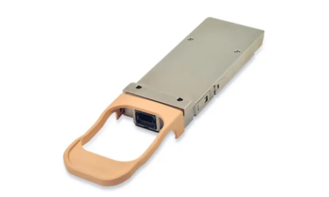
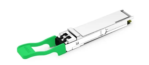
When applying the optical module, pay attention to holding it lightly and preventing it from falling; when inserting the optical module, push it in by hand, and do not use other metal tools; when pulling it out, open the pull ring to the unlocked position and then pull the pull ring, and do not use other metal tools.

Figure 1-6 Schematic diagram of optical module installation method
When cleaning the optical port, use special cleaning swabs, and do not use other metal substances to insert into the optical port.

Subscribe to the newsletter
for all the latest updates.


2-5# Building, Tongfuyu Industrial Zone, Aiqun Road, Shiyan Street, Baoan District, Shenzhen. China