

 Knowledge Base +
  2024.01.05
What wavelengths correspond to single mode and multimode? The question then becomes, what is the relationship between the output ranges of the single transverse mode or multiple transverse modes and the longitudinal mode of the (stimulated emission) optical amplifier?
A: Theoretically there is no correspondence. For two-dimensional considerations, the two are orthogonal. 1310nm lasers can be single or multiple transverse modes. Similarly, 850nm and 1550nm lasers can be designed as single or multiple transverse modes.
However, we should take into account that a specific industry chain has been formed in practical applications, which has the best price/performance ratio in some special scenarios. For example, in fiber-based communication scenarios, multi-transverse mode lasers with a wavelength of 850 nm have a low-cost advantage, while single-transverse mode lasers based on 1310 nm or 1550 nm have excellent transmission performance with low dispersion/low Losses in the fiber.
For example, in the LIDAR industry, for edge-emitting lasers, there is no need to consider the characteristics of single transverse mode for TOF or AM scenarios. Multimode EEL edge-emitting long wavelength lasers can be manufactured to increase power and reduce eye safety risks. Light has a direction of transmission, and the mode along the direction of transmission is the longitudinal mode, which is a frequency-dependent property of lasers based on "time interference".
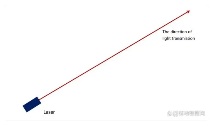
Direction of light transmission in lasers
The light field distribution in the cross-section perpendicular to the direction of transmission is the transverse mode, which is based on some of the distribution properties of "spatial interference" in lasers.
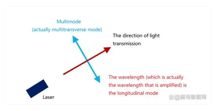
Anyone who has designed a laser knows that there are two types of solutions to the laser equation - temporal and spatial.
Spatial and temporal dimensions of lasers
The transverse mode is based on the energy distribution in space. This is the distribution that can be seen in real life, which we will talk about later. The longitudinal mode is an energy distribution based on time. Light travels at the speed of light and has several parameters such as wavelength, (optical) velocity, fluctuation time and distance. The wavelength is not visible to the naked eye, so it needs to be tested with a spectrometer, which is actually an optical spectrometer. Frequency of light x wavelength of light = speed of light in vacuum C, where C is a constant. Therefore, a spectrum analyzer can be used to test the frequency (e.g. ~300 THz corresponds to 1.3 μm wavelength, ~200 THz corresponds to 1.5 μm wavelength) and calculate the wavelength.
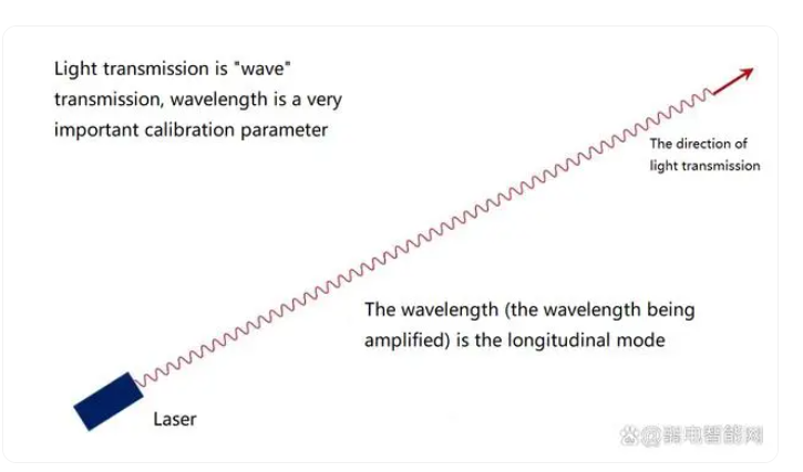
Light propagation is wave propagation
In this article, we refer to wavelength as a range of wavelengths.
Wavelength is a range
The wavelength range is determined by the gain material. Within this range, it is the function of the resonant cavity to select a specific wavelength for interference. Interference can act as amplification.
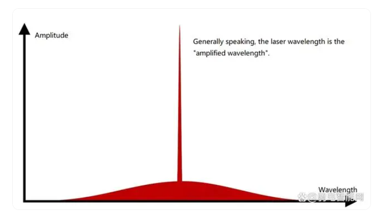
A resonant cavity has a cavity length, and the gratings in DFBs and VCSELs have "tiny" cavity lengths. The cavity length and the wave speed of the light can be used to calculate the reflection time of the light, and the time-based interference is the longitudinal model. These longitudinal models have a different focus in our context.
Resonant cavities and gain are made together and are the choice for most lasers in optical transceivers, such as VCSELs, DFBs, EMLs, and other chips. The resonator (the cavity used for interference amplification) determines which wavelengths are amplified. The same type of material system is selected for the resonator cavity and gain material, such as GaAs material system for VCSEL, InP material system for DFB, etc.
Different systems are used for the resonant cavity and the gain material, for example, a GaAs system for the gain and a silicon system for the resonant cavity. This is Huawei's process of epitaxial GaAs on silicon substrate and making InAs quantum dots in OFC2023, or HP's silicon-based quantum dot laser. Using InP for gain and silicon as a resonator is Intel's silicon-based integrated laser. Gain material: determines the wavelength range. When the resonant cavity and the gain material are made independently, we have an external cavity laser, i.e. a laser consisting of a resonant cavity "independent of the gain".
Returning to transverse mode, single mode and multimode are used in the industry to refer to transverse mode, which is the spatial distribution of energy. While single mode and multimode are important in fiber optic communications, the TOF method for LIDAR is not. When there are multiple energy peaks, it is multimode, and when there is only one energy peak, it is single mode. Spatial fluctuation is visible with eyes, when our laser pointer shines on the screen, we can see the distribution of bright spots, which is the reflection of transverse mode.
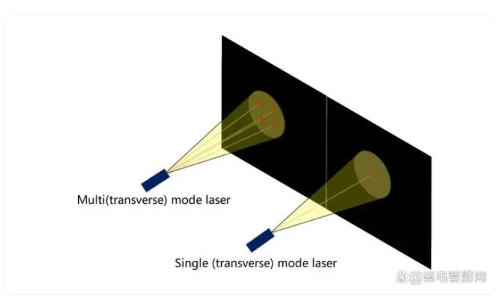
The VCSEL in the optical module is a multi-mode laser, which means that there are multiple bright spots.The full name of VCSEL is vertical cavity surface emitting laser. The vertical cavity surface refers to the relative coordinates of the wafer. The resonant cavity is perpendicular to the wafer surface and is called the vertical cavity. The direction of the resonant cavity is related to the output direction of the laser, which determines the light output direction of the laser without special treatment. Emission perpendicular to the wafer surface can be realized, either surface emission or bottom emission.
Single-mode lasers generally emit from the side, either from the left or right side, or from both sides simultaneously. For edge emission, the output direction of light is realized by the transverse resonant cavity without any other additional processing, the output wavelength range is realized by the gain material, and the transverse spot is determined by the spatial structure of the output waveguide.
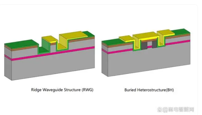
Two common types of waveguide structures used to confine single mode
The space of light also "fluctuates". With the right width, there are no multiple bright spots. For most optical communication laser designs, InP material systems have a waveguide width of about 2μm, which is a common structure for single-mode confinement.
Since it is common, it is not unique. If the space-limited structure is widened, multiple transverse modes can occur. This was common in early lasers. Then it became easy to fabricate single modes in optical communications and people forgot about it.
In recent years there has been renewed talk of wider waveguides because of the need to increase output power. For example, FiberMall uses multimode to realize DFB+SOA cascade, and then uses virtual waist to realize single mode. And the 5μm width lasers made by Huawei in recent years are essentially multi-transverse mode with the aim of increasing output power.
Another example is the TOF method in the field of LIDAR, which prefers to consider high power compared to single mode and multi-mode. They don't need to be transmitted over optical fiber, so there is no need to consider this aspect. The figure below shows a multi-transverse mode laser with the waveguide width stretched wide for edge emission.
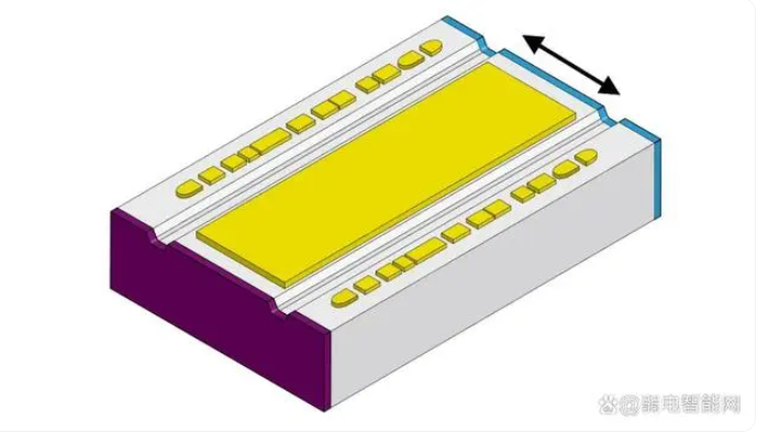
Edge-emitting multi-mode laser for LIDAR applications
In summary, as far as edge-emitting lasers are concerned, fiber optic communications have a requirement for single mode, which is achievable. Some application scenarios have localized multimode designs, and we need additional processing to get back to single mode again. This move is essentially to meet the needs of fiber optic communications.
Subscribe to the newsletter
for all the latest updates.
2-5# Building, Tongfuyu Industrial Zone, Aiqun Road, Shiyan Street, Baoan District, Shenzhen. China
