CHS
CHS Walsun Mall
Support

 Knowledge Base +
  2023.12.04
The maximum length of a QSFP (Quad Small Form-factor Pluggable) cable is typically around 30 meters for copper cables and up to 100 meters for optical cables. However, the actual maximum length may vary depending on the specific type and quality of the cable, and should be verified with the manufacturer's specifications.
Table 1. Cisco QSFP40G portfolio
Product | Type | Connector Type |
QSFP-40G-SR4-S | 40GBASE-SR4, 4 lanes, 850 nm MMF | MPO-12 |
QSFP-40G-SR4 | 40GBASE-SR4, 4 lanes, 850 nm MMF | MPO-12 |
QSFP-40G-SR-BD | 40GBASE-SR-BiDi, duplex MMF | LC |
QSFP-40G-BD-RX | 40GBASE-SR-BiDi, duplex MMF, Monitor | LC |
FET-40G | Fabric Extender, 4 lanes, 850 nm MMF | MPO-12 |
QSFP-40G-CSR-S | 40GBASE-SR-, duplex MMF | LC |
QSFP-40G-CSR4 | 40GBASE-CSR4, 4 lanes, 850 nm MMF | MPO-12 |
WSP-Q40GLR4L | 40GBASE-LR4-Lite, 1310 nm, SMF | LC |
QSFP-40G-LR4-S | 40GBASE-LR4, 1310 nm, SMF | LC |
QSFP-40G-LR4 | 40GBASE-LR4, 1310 nm, SMF with OTU3 data-rate support | LC |
QSFP-4X10G-LR-S | 4x10GBASE-LR | MPO-12 |
QSFP-40G-ER4 | 40GBASE-ER4, 1310 nm, SMF with OTU3 data-rate support | LC |
QSFP-H40G-CU | QSFP to QSFP copper direct-attach cables | - |
QSFP-H40G-ACU | QSFP to QSFP copper direct-attach active cables | - |
QSFP-4SFP10G-CU | QSFP to 4 SFP+ copper break-out cables | - |
QSFP-4X10G-AC | QSFP to 4 SFP+ copper break-out active cables | - |
QSFP-H40G-AOC | QSFP to QSFP active optical cables | - |
QSFP-4X10G-AOC | QSFP to four SFP+ active optical breakout cables | - |
CVR-QSFP-SFP10G | QSFP 40G to SFP+ 10G adapter | - |
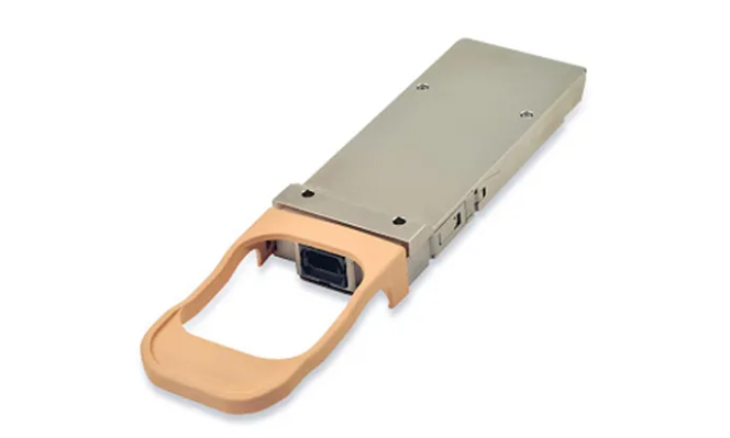
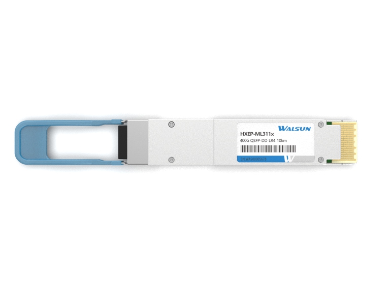
QSFP Connectors and Cable Assemblies
The acronym QSFP stands for Quad Small Formfactor Pluggable, and QSFP is a family of connectors and cable assemblies that share a mating interface. A mating interface is where the two separable pieces of a connector system that come together to form an interconnect. QSFP’s mating interface is a card edge defined in a multi-source agreement called INF-8438i. A card edge mating interface is the end of a printed circuit board with exposed and plated pads. These pads make contact with the beams of a mating QSFP connector. The card edge layout is shown below.

The QSFP connector is quite small: 12.5mm x 18.2mm x 5.6mm. However, the connector is not used by itself. A press-fit cage is assembled over the connector to guide and latch the QSFP cable assembly. For some QSFP arrays, the cage is integrated with the connector so both can be placed on the PCB simultaneously.

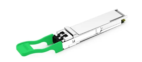
The cable is unlatched by pulling the pull-tab. The pull-tab is shown below in green. However, the shape, size, and color of the pull-tab is customizable. Occasionally, we’ll even put a custom emboss on the die-cast backshell with the customer name and logo. This allows the customer to sell the product as their own.
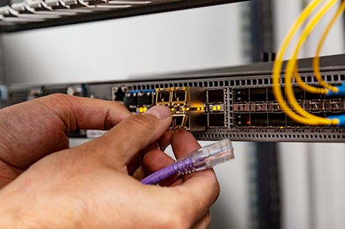
QSFP cable assemblies are used in networking devices such as patch panels, switches, and host card adaptors (HCA) and compute devices such as servers. The host card adaptor is connected to a computer via a PCIe slot. Since the data needs to pass through the PCIe slot, the maximum throughput can be limited to the PCIe protocol implemented on the HCA.

QSFP connectors and cable assemblies have many options/configurations, and performance levels. The table below summarizes these performance levels.

Any QSFP cable assemblies can be plugged into any QSFP or QSFP DD connector. However, QSFP DD cable assemblies can only be used with QSFP DD connectors.
The cages have many options. A QSFP connector cage could house 1 to 6 connectors. The connector configuration could be one row and up to six columns or two rows up to three columns. In this way you can configure a 36-port switch in multiple ways. For example, you could use six 1x6 connector and cage arrays in a belly-to-belly configuration, or you could use six 2x3 connector and cage arrays that are all mounted on the same layer.

Optional heatsinks and light-pipes are available. These get assembled with the cage to move heat away from the QSFP module or to get access to network activity, respectively. The heatsinks come in fin and pin styles and have three available heights: 4.2mm, 6.5mm, and 13.5mm. Similarly, the light-pipes come in two options: 1.4mm diameter or 2.6mm square.

QSFP interconnects include direct attach copper (DAC), active optical cables (AOC), optical modules, and active copper cables (ACC). DACs are the least expensive option. They provide connectivity that relies on signal conditioning from the host. The maximum length achievable depends on the insertion loss of the cable assembly, which is driven by the IEEE specifications (see below) and the cable assembly insertion loss is determined by its length and cable gauge (AWG). The size of the wire is inversely proportional to its AWG. The table below shows AWG vs wire diameter for QSFP cable assemblies. As you can see from the table, Amphenol’s QSFP cable can be as small as 34AWG and as large as 24AWG. There are mechanical limitations that make going to 24AWG impossible for some QSFP applications. Each QSFP cable assembly datasheet will provide these limits.
Subscribe to the newsletter
for all the latest updates.


2-5# Building, Tongfuyu Industrial Zone, Aiqun Road, Shiyan Street, Baoan District, Shenzhen. China